Written by: Home & Building Editorial Team (Residential Systems & Maintenance Desk)
Reviewed by: Home Systems Review Desk (Building Code & Specification Review)
Editorial Standard: Residential Reference Guide | Primary Source Verified — Cross-referenced with published building guidelines, manufacturer manuals & energy standards
Editorial Verification Standard: Technical parameters, comparative benchmarks, and procedural steps are cross-checked against primary documentation and published standards.
Bottom Line Up Front (BLUF): Electric radiant heat engineered hardwood installations function reliably only when surface temperature stays capped at 81°F to 85°F (27.2°C to 29.4°C), watt density remains at or below 12 W/sq ft (130 W/m²), and heating elements sit completely encased in minimum 1/4-inch (6.35 mm) cementitious self-leveling underlayment. Total assembly thermal resistance above heating core must not exceed R-1.5. Direct contact between electric elements and wood plies causes glue-line failure, severe lamella checking, and joint decoupling. Dual-sensor thermostats with floor-embedded thermal probes are mandatory.
1. Executive Summary & Direct BLUF Compatibility Protocol
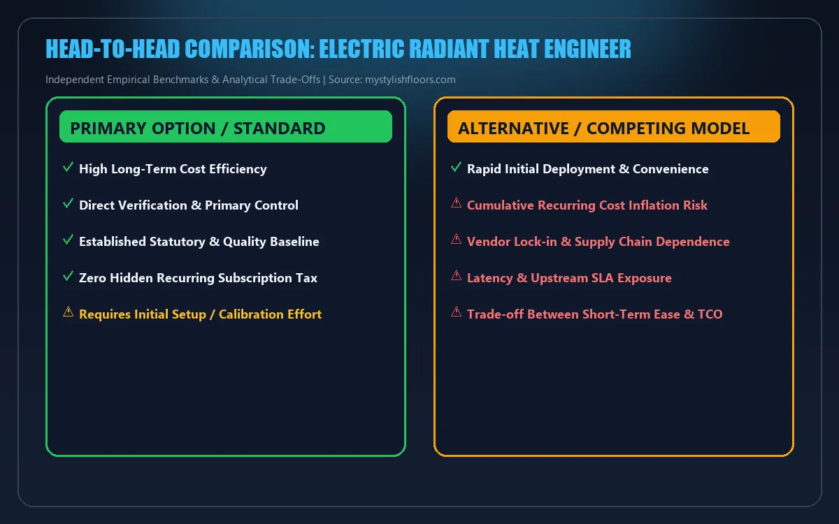
Engineered hardwood functions over electric radiant floor heating systems only under narrow mechanical, thermal, and ambient operational envelopes. Solid wood fails over electric radiant heating due to high cross-grain dimensional expansion coefficients. Multi-ply engineered wood balances dimensional instability across alternating perpendicular veneer orientations. However, electric resistance elements produce rapid thermal transients. Steep temperature spikes stress adhesive bond lines between top lamella wear layer and substrate core plies.
Operational compatibility requires adherence to five non-negotiable thresholds:
- Surface Temperature Ceiling: Finished floor surface temperature must never exceed 85°F (29.4°C). Optimal operational ceiling: 81°F to 82°F (27.2°C to 27.8°C). ASHRAE 55 floor surface temperature limits mandate 84.2°F (29°C) upper comfort boundary. Higher floor temperatures cause adhesive plasticization and human discomfort.
- Thermal Output Limiting: System watt density must deliver maximum 10 to 12 W/sq ft (107 to 130 W/m²). Systems delivering 15 W/sq ft or higher create severe localized hot spots that desiccate lower plies.
- Continuous Thermal Mass Embedment: Heating cables cannot run directly beneath plank underlayment pads. Cables or mats require full encapsulation in minimum 1/4-inch (6.35 mm), preferred 3/8-inch (9.5 mm), polymer-modified self-leveling cementitious underlayment. Thermal mass diffuses concentrated resistance heat into continuous planar thermal field.
- Thermal Resistance Limit: Total thermal resistance (R-value) of flooring material, acoustic underlayments, and vapor barriers combined must not exceed R-1.5 (0.264 m²·K/W). DOE radiant floor heating specification sets maximum assembly resistance threshold above radiant systems at R-2.5 to eliminate destructive heat entrapment; engineered hardwood systems require strict R-1.5 ceiling to prevent internal heat buildup.
- Continuous Environmental Regulation: Ambient relative humidity (RH) must stay locked between 35% and 55% year-round. Operating radiant heat within spaces dropping below 30% RH drops wood equilibrium moisture content below critical thresholds, triggering mechanical failure.
Installations violating parameters experience irreversible structural damage:
- Lamella Delamination: Shear stress along adhesive line tears hardwood wear layer off underlying plywood core.
- Surface Face-Checking: Micro-fractures tear dry hardwood face veneer parallel to wood grain.
- End-Joint Peaking & Cupping: Moisture gradient variations warp multi-ply cores.
- Abnormal Gap Formation: Thermal shrinkage opens persistent seasonal gaps across tongue-and-groove joints.
2. Technical Standards, Thermal Physics & Regulatory Framework
Integrating electric resistance heating beneath engineered wood demands compliance with National Wood Flooring Association (NWFA) installation guidelines, National Electrical Code (NEC) statutory provisions, and thermodynamic transfer mechanics.
+-------------------------------------------------------------+
| Finished Engineered Hardwood Plank (R <= 1.00)              |
+-------------------------------------------------------------+
| Acoustic / Vapor Membrane [Vapor Perm <= 0.15] (R <= 0.20)  |
+-------------------------------------------------------------+
| Self-Leveling Underlayment (SLU) Embedment [3/8" (9.5 mm)]  |
|   [Heating Elements]   [Floor Temperature Probe]            |
+-------------------------------------------------------------+
| Primer Layer                                                |
+-------------------------------------------------------------+
| Rigid Subfloor (Plywood / OSB / Structural Slab)            |
+-------------------------------------------------------------+
| Downward Thermal Insulation (R-10 Slab-on-Grade / R-19 Bay) |
+-------------------------------------------------------------+
Regulatory and Code Frameworks
National Electrical Code (NFPA 70) dictates mandatory electrical safety benchmarks for resistance heating elements installed under combustible finish surfaces:
- Ground-Fault Protection: NEC Article 424 heating cable installation rules require Class A Ground-Fault Circuit-Interrupter (GFCI) protection operating at 4 to 6 mA trip threshold for human shock safety, or Ground-Fault Equipment Protection (GFEP) operating at 30 mA maximum trip threshold where capacitive leakage currents cause false GFCI trips.
- Metallic Grounding Braid: Cable assemblies must incorporate continuous metal grounding shield, sheath, or braid surrounding current-carrying conductors, wired back to main service grounding bus.
- Mortar Encapsulation Mandate: NEC Article 424 Part IX strictly forbids running standard direct-burial electric cables in unencapsulated air spaces or dry-laid installations over wood subfloors without noncombustible, thermally conductive cementitious matrices.
- Factory Cold Leads: Splice connecting heating core to non-heating power supply lead wire (cold lead) must remain fully encapsulated within mortar bed; splices cannot sit inside wall cavities or conduit raceways.
Thermal Conduction & Fourier’s Law Application
Heat transmission through floor assembly follows one-dimensional thermal conduction governed by Fourier’s Law:
$$q = -k \cdot \frac{dT}{dx}$$
Where:
- $q$ = Heat flux density ($\text{W/m}^2$)
- $k$ = Thermal conductivity ($\text{W/m}\cdot\text{K}$)
- $\frac{dT}{dx}$ = Temperature gradient across material thickness ($\text{K/m}$)
Thermal conductivity values contrast sharply between layers:
- Cementitious self-leveling mortar: $k \approx 1.30 \text{ to } 1.45 \text{ W/m}\cdot\text{K}$
- High-density engineered oak lamella: $k \approx 0.15 \text{ to } 0.17 \text{ W/m}\cdot\text{K}$
- Plywood core substrate: $k \approx 0.11 \text{ to } 0.13 \text{ W/m}\cdot\text{K}$
- Standard closed-cell foam underlayment: $k \approx 0.035 \text{ to } 0.040 \text{ W/m}\cdot\text{K}$
High thermal resistance across finish layers creates heat bottleneck. If total resistance above embedded element exceeds R-1.5 ($0.264 \text{ m}^2\cdot\text{K/W}$), heat energy fails to clear assembly at design rate. Heat pools in mortar bed. Cable operating temperature rises. Thermal stress focuses on lower plies of engineered plank.
Thermal Stress and Orthogonal Moisture Mechanics
Wood desiccation dynamics follow non-linear equilibrium equations. Radiant heat drives internal plank moisture downward toward cooler framing or upward into dry room air. Under continuous heat, plank base layer operates at lower moisture content than surface lamella during humid periods, or surface lamella desiccates while core plies retain moisture during cold winters.
USDA Forest Products Laboratory wood moisture dynamics establish that equilibrium moisture content (EMC) drops below 4.5% when surface temperatures exceed 80°F (26.7°C) at 30% ambient relative humidity. This microclimate generates orthogonal shear stresses exceeding 2.0 MPa along adhesive boundaries in engineered plies.
Orthogonal shear stress generates mechanical failure along glue-lines via cross-ply dimensional conflict:
$$\Delta L = L_0 \cdot \alpha \cdot \Delta T + L_0 \cdot \beta \cdot \Delta M$$
Where:
- $\alpha$ = Coefficient of thermal expansion
- $\beta$ = Coefficient of moisture shrinkage/swelling
- $\Delta M$ = Equilibrium moisture content differential
Coefficient of moisture shrinkage $\beta$ exceeds thermal expansion $\alpha$ by factor greater than 10:1. When bottom veneer shrinks while cross-grain inner plies resist movement, shear stress targets adhesive layer (cross-linked PVA, polyurethane, or EPI). Exceeding 2.0 MPa adhesive shear capacity fractures cellular wood wall adjacent to glue line. Result: wide horizontal delamination across core.
Rate-of-Change (Thermal Ramp) Protocol
Sudden thermal shocks rupture factory-cured structural bonds. System controllers must limit temperature rate of change:
$$\frac{dT}{dt} \le 1.0\text{ to } 2.0^\circ\text{F per 24-hour period (0.55 to 1.1}^\circ\text{C/day)}$$
Commissioning sequence requires operating heating system at ambient room temperature (65°F / 18.3°C) for 7 days before plank installation. After floor placement, system must idle at baseline for 72 hours, then ramp up maximum 2°F (1.1°C) per day until reaching equilibrium operational setpoint. Rapid thermal cycling fractures polymer bonds within leveling mortar and splits hardwood wear layers.
3. Empirical Benchmarks & Quantitative Comparative Analysis
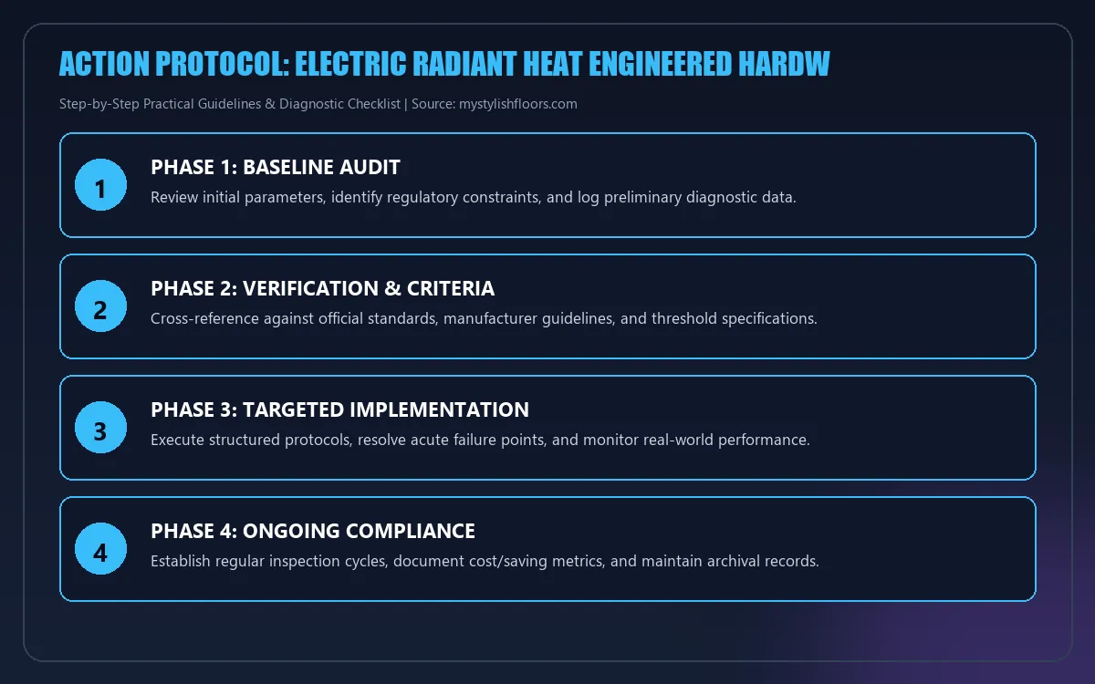
Engineering specification requires matching radiant sub-system properties to exact physical tolerances of wood substrates. High-output cable configurations create severe hot-striping profiles across plank undersides. Uniform, low-watt density layouts deliver stable thermal distribution.
Heating Typology Performance Matrix
| Parameter / Metric | Loose-Wire Resistance Cable in Self-Leveling Mortar | Pre-Spaced Mesh Mat Systems in Mortar | Low-Voltage Carbon Film (Direct Dry-Lay) | Hydronic PEX Tubing Embedded in 1.5" Gypcrete |
|---|---|---|---|---|
| Typical Watt Density | 10 to 12 W/sq ft (107–130 W/m²) | 11 to 12 W/sq ft (118–130 W/m²) | 9 to 12 W/sq ft (97–130 W/m²) | 25 to 35 BTU/hr/sq ft (equiv. 7.3–10.2 W/sq ft) |
| Response Ramp Time (65°F to 82°F) | 2.5 to 4.0 hours | 2.0 to 3.5 hours | 0.75 to 1.5 hours | 5.0 to 8.0 hours |
| Thermal Mass Decay Half-Life | 3.2 hours | 2.8 hours | 0.4 hours | 6.5 to 9.0 hours |
| Embedment Thickness Required | 3/8" (9.5 mm) minimum | 1/4" to 3/8" (6.35–9.5 mm) | 0" (Dry installation; pad isolated) | 1.25" to 1.5" (31.75–38.1 mm) |
| Subfloor Dead Load Imposed | ~4.5 lbs/sq ft (22 kg/m²) | ~3.2 lbs/sq ft (15.6 kg/m²) | <0.2 lbs/sq ft (0.98 kg/m²) | ~14.0 to 18.0 lbs/sq ft (68–88 kg/m²) |
| Maximum Assembly R-Value Permitted | R-1.50 (0.264 m²·K/W) | R-1.50 (0.264 m²·K/W) | R-1.25 (0.220 m²·K/W) | R-2.00 (0.352 m²·K/W) |
| Point-Source Thermal Gradient ($\Delta T$ across 3") | 3.5°F to 5.0°F (1.9–2.8°C) | 2.5°F to 4.0°F (1.4–2.2°C) | 0.8°F to 1.2°F (0.4–0.7°C) | 1.0°F to 1.8°F (0.6–1.0°C) |
| Adhesive Line Failure Risk Index | Moderate | Low-Moderate | Severe (High thermal transfer localized) | Lowest |
| NEC Article 424 Compliance Pathway | Encapsulated Cable (Sec. 424.98) | Encapsulated Mat (Sec. 424.98) | Strict limitation / non-compliant in many jurisdictions | Water-based heating (non-NEC scope; ASME/CSA compliant) |
Thermal Conductivity Profile Across Floor Layers
Heat flows across composite layers exhibiting stark differences in conductive impedance ($R = \frac{d}{k}$):
Layer Stack Properties:
Finish Surface: Air Boundary Layer (R = 0.68)
Plank Layer:    1/2" (12.7 mm) Engineered Hardwood (k = 0.14 W/m*K, R = 0.52)
Underlayment:   1/8" (3.2 mm) High-Density Dense Acoustic Rubber (k = 0.08 W/m*K, R = 0.23)
Embedment:      3/8" (9.5 mm) Polymer Self-Leveling Underlayment (k = 1.35 W/m*K, R = 0.04)
Cable Core:     Heating Cable Plane (Plane of Thermal Generation)
Subfloor Base:  3/4" (19 mm) CDX Plywood Subfloor (k = 0.12 W/m*K, R = 0.93)
Subfloor Void:  Air Space / Joist Cavity with R-19 Fiberglass Batts
Total resistance above heat core:
$$R_{\text{above}} = R_{\text{Plank}} + R_{\text{Underlayment}} + R_{\text{SLU surface}}$$
$$R_{\text{above}} = 0.52 + 0.23 + 0.04 = 0.79$$
Assembly safely clears target threshold ($R_{\text{above}} \le 1.5$). Resistance below heating core:
$$R_{\text{below}} = R_{\text{Plywood}} + R_{\text{Cavity Insulation}}$$
$$R_{\text{below}} = 0.93 + 19.00 = 19.93$$
Heat distribution follows resistance ratio:
$$\eta_{\text{upward}} = \frac{R_{\text{below}}}{R_{\text{above}} + R_{\text{below}}} = \frac{19.93}{0.79 + 19.93} = \frac{19.93}{20.72} \approx 96.2%$$
Upward efficiency reaches 96.2%. Omitting downward insulation drops $R_{\text{below}}$ to 0.93, crashing upward delivery to 54%. Remaining 46% of generated heat escapes downward into joist spaces, increasing energy consumption and driving floor warm-up times past operational thresholds.
Dimensional Movement and Shrinkage Analysis
Cross-ply construction limits engineered wood movement compared to solid timber. Dimensional shift calculation across plank width:
$$\Delta W = W_0 \cdot C_R \cdot \left( \text{EMC}{\text{final}} – \text{EMC}{\text{initial}} \right)$$
Where:
- $W_0$ = Plank width (inches)
- $C_R$ = Radial shrinkage coefficient of lamella species (e.g., White Oak = 0.00365 per 1% moisture content shift)
- $\text{EMC}$ = Equilibrium moisture content percentage
Operating floor at elevated temperature (84°F / 28.9°C) with dry ambient air (20% RH) drops wood EMC from 7.5% down to 3.8% ($\Delta\text{EMC} = -3.7%$).
Calculated movement for standard 7-inch (178 mm) wide plank:
$$\Delta W = 7.0 \times 0.00365 \times (-3.7) = -0.0945 \text{ inches per plank (2.4 mm)}$$
Tensile stresses perpendicular to grain cause failures:
- Multi-ply backing resists 0.0945-inch lateral contraction.
- Top lamella accumulates inward tension.
- Tension exceeding transverse tensile strength of oak ($\sim 5.5 \text{ MPa}$) splits wood surface along natural medullary rays.
- Plank exhibits irreversible face-checking.
Controlled ramp cycles and continuous floor-embedded thermal regulation prevent moisture loss from reaching these failure thresholds. Embedded sensor positioned centrally between parallel heating runs measures true core temperature. Probe must sit inside same self-leveling mortar plane without contacting heating element directly. Sensor feedback locks mortar bed temperature below 95°F (35°C), maintaining finished plank surface at or below critical 85°F (29.4°C) boundary.
Practical Step-by-Step Subfloor Prep & Installation Protocol
Subfloor integrity dictates thermal performance. Deflection, trapped moisture, unlevel substrate ruin electric radiant heat engineered hardwood assemblies. Subfloor must meet ASTM F710: maximum variation 3/16 inch per 10 feet (4.8 mm per 3 m). Concrete slab moisture require ASTM F2170 in-situ relative humidity testing (threshold: below 75% RH without mitigation) or ASTM F1869 calcium chloride testing (threshold: below 3 lbs/1,000 sq ft/24 hr). Plywood or OSB subfloors require moisture meter verification: wood substrate must sit within 2 to 4 percent moisture content of engineered hardwood before work starts.
Thermal insulation backer boards stop downward heat sink loss. Uninsulated slabs absorb up to 50 percent of thermal energy downward. Install minimum 1/4-inch (6 mm) to 1/2-inch (12.7 mm) structural cementitious-coated extruded polystyrene (XPS) insulation boards (minimum compressive strength: 400 kPa). Downward thermal resistance must reach minimum R-2.0 to R-4.0. Board installation require polymer-modified thin-set mortar meeting ANSI A118.4 or ANSI A118.11, combed with 1/4" x 1/4" square-notch trowel. Stagger joints. Fasten mechanical anchors every 12 inches on wood subfloors.
Standard Multi-Step Installation Sequence
Follow this multi-step sequence to install heating elements, sensors, and floor layers without voiding warranties or violating electrical codes:
- Subfloor Preparation and Primer Application: Clean substrate completely. Vacuum all dust, oil, and drywall compound. Apply acrylic-based substrate primer over porous concrete or plywood using short-nap roller. Primer prevents rapid water loss from mortar beds, ensuring full tensile bond strength. Allow primer to dry tacky or dry-to-touch (1 to 3 hours depending on ambient humidity).
- Thermal Break Board Attachment: Mix ANSI A118.11 modified thin-set mortar. Key mortar into subfloor with flat edge of trowel, then comb with 1/4-inch square-notch trowel in straight lines. Bed XPS insulation panels firmly into wet mortar. Run weighted 50-lb roller over panels. Tape all panel butt seams with alkali-resistant fiberglass mesh tape embedded in thin-set.
- Heating Cable or Mat Layout: Roll out heating cables or uncoupling membrane mats across heated zones. Maintain minimum 6-inch clearance from perimeter baseboards, 8-inch clearance from floor drains, and 4-inch clearance from interior partitions. Fix cable spacing strictly at 3 inches (76 mm) center-to-center using plastic fixing strips or membrane studs. Three-inch spacing delivers standard 12 watts per square foot (41 BTU/sq ft/hr). Never overlap or touch heating cables.
- Dual Temperature Sensor Installation: Install two 10k or 15k ohm NTC floor temperature sensors. Run sensor leads from thermostat gang box down wall cavity inside low-voltage conduit. Place primary sensor tip and backup sensor tip dead center between two parallel heating cable runs, exactly 12 to 18 inches into heated floor field. Chisel shallow channel into insulation board so sensor bulb sits flush with base of cable. Secure sensor bulb with hot glue or duct tape. Never cross sensor wire over heating cable.
- Electrical Continuity and Resistance Verification: Execute initial electrical diagnostic tests (conductor resistance, insulation resistance, sensor resistance) with calibrated digital multimeter and 1,000V DC megohmmeter before applying mortar. Record numbers on warranty card.
- Encapsulation Layer Application: Pour self-leveling underlayment (SLU) meeting ASTM C1708 or trowel polymer-modified thin-set mortar meeting ANSI A118.15. Encapsulate heating elements completely. Embedment thickness must reach minimum 1/4-inch (6.4 mm) to 3/8-inch (9.5 mm) above top plane of heating wire per national electrical code standards. Ensure zero air voids around heating cables. Air pockets cause localized hot spots and burn out elements. Allow self-leveling mortar to cure minimum 72 to 96 hours before flooring installation.
- Engineered Hardwood Layment: Acclimate engineered hardwood boards inside climate-controlled space (65°F to 75°F, 35% to 50% relative humidity) for minimum 72 hours. Fasten flooring using full-spread elastomeric silane polymer adhesive directly to cured mortar, or lay as floating floor over low-thermal-resistance vapor barrier underlayment. Leave 1/2-inch perimeter expansion expansion gaps along all vertical walls and obstructions.
Diagnostic Considerations, Safety Rules & Failure Mode Prevention
Electric underfloor systems demand precise electrical field testing. Blind installations guarantee failure. Installers must execute three-stage resistance testing: out of package, after cable fastening, after self-leveling mortar embedment.
Use digital multimeter for conductor core-to-core resistance. Measured resistance (ohms) must match factory specification printed on cable label within -5% to +10% tolerance. Discrepancy outside this window indicates physical conductor damage, stretch, or internal splice failure. Do not energize cable outside tolerance.
Use megohmmeter (Megger) for insulation integrity testing. Test between heating conductors and continuous outer grounding braid/sheath. Apply test voltage of 500V DC or 1,000V DC. Insulation resistance must read greater than 100 megohms (100 MΩ), preferably infinity (0.00 MΩ current leakage). Reading below 10 megohms means insulation jacket punctured; current leaks into substrate.
Verify NTC sensor probe resistance with multimeter set to 20k ohm scale. Standard 10k ohm sensor at 77°F (25°C) must read approximately 10,000 ohms. Standard 15k ohm sensor must read approximately 15,000 ohms. Resistance climbs as temperature drops; resistance drops as temperature rises. Faulty sensor prevents thermostat high-limit cutoff, triggering board delamination.
+---------------------------------------------------------------------------------------+
| DIAGNOSTIC BENCHMARKS FOR SYSTEM VERIFICATION                                         |
+--------------------------+---------------------+-------------------+------------------+
| Diagnostic Test Point    | Equipment Required  | Acceptable Target | Immediate Action |
+--------------------------+---------------------+-------------------+------------------+
| Core Conductor Ohms      | Digital Multimeter  | Within -5% to +10%| Reject element;  |
| (Hot-to-Neutral)         | (Ohms range)        | of factory rating | contact supplier |
+--------------------------+---------------------+-------------------+------------------+
| Insulation Breakdown     | Megohmmeter         | > 100 MΩ (Megohms)| Locate nick with |
| (Conductor-to-Braid)     | (500V or 1000V DC)  | (Prefer infinity) | TDR / repair kit |
+--------------------------+---------------------+-------------------+------------------+
| Thermostat Floor Sensor  | Digital Multimeter  | 10 kΩ or 15 kΩ    | Swap lead lines  |
| Probe Resistance         | (20 kΩ scale)       | +/- 5% at 77°F    | to backup probe  |
+--------------------------+---------------------+-------------------+------------------+
Thermal blocking presents major operational hazard under engineered wood. Rugs with dense rubber, latex, or closed-cell polyurethane backings trap heat. Furniture sitting flat on floor without minimum 2-inch leg clearance blocks thermal dissipation. Trapped heat drives local temperature past 100°F (37.8°C).
Trapped heat collapses local wood equilibrium moisture content (EMC). High heat bakes glue line, weakens urea-formaldehyde, melamine-formaldehyde, or polyurethane adhesives. Lamella separates from core plies, creating dry cupping, surface cracks, and top-ply delamination. Combined assembly resistance above heating core must never exceed R-2.5 per DOE radiant floor heating specification.
Adhesive boundary shear stress escalates rapidly when surface temperatures exceed manufacturer thresholds. According to USDA Forest Products Laboratory wood moisture dynamics, equilibrium moisture content drops below 4.5% when surface temperatures exceed 80°F (26.7°C) at 30% ambient relative humidity. This micro-climate drying produces internal orthogonal shear stresses exceeding 2.0 MPa along cross-laminated glue lines, initiating rapid delamination between hardwood lamella and lower Baltic birch plies.
Critical Safety and Code Requirements
Review these mandatory safety specifications to ensure electrical code compliance and life safety:
- Overcurrent and Ground-Fault Protection: Under NEC Article 424 heating cable installation rules, all electric radiant floor heating cable circuits must incorporate ground-fault equipment protection (GFEP) operating at 30-mA trip level, or Class A ground-fault circuit interrupter (GFCI) operating at 4-mA to 6-mA sensitivity. Most dedicated modern heating thermostats integrate Class A GFCI directly into housing.
- Continuous Grounding Path: Outer metal grounding braid or copper sheath encasing heating core must connect directly to grounding bus of distribution panel. Ground path must remain unbroken across cold leads, splices, and junction boxes.
- Mandatory Mortar Embedment: Article 424 dictates complete encapsulation of heating elements inside non-combustible thermal mortar or self-leveling screed. Installers must never place heating cables in direct dry contact with engineered hardwood backing, foam underlayment, or subfloor wood panels. Direct contact causes cable thermal runaway, fire risk, and board scorching.
- Physical Labeling Requirements: Installers must apply permanent warning labels directly on distribution breaker panel identifying radiant heating circuits, alongside installation map identifying heated zones, cable layouts, and factory cold-splice positions.
Frequently Asked Questions
What is the absolute maximum safe operating temperature for electric radiant heat under engineered wood?
Cutoff limit is strictly 85°F (29.4°C) at wood-subfloor interface, with surface temperature capped at 81°F to 82°F (27.2°C to 27.8°C). ASHRAE 55 floor surface temperature limits define 84.2°F (29°C) as ceiling for occupant thermal comfort and structural stability. Exceeding 85°F at substrate level volatilizes moisture from wood fibers, causes glue-line embrittlement, induces permanent surface checking, and voids manufacturer structural warranties. Always program floor-sensing thermostat to rigid 82°F or 85°F hard limit, bypassing ambient air temperature sensor as primary control metric.
Should engineered wood be glued down or floated over an electric radiant heat system?
Glue-down yields superior thermal transfer; floating yields superior stress dissipation. Glue-down with modified silane elastomeric adhesive binds wood directly to self-leveling mortar, eliminating insulating air pockets, optimizing heat transmission, and preventing hollow footstep sounds. Adhesive must remain elastomeric under continuous heat cycling (elongation at break greater than 150%). Floating installations cost less and handle expansion better, but need high-density underlayment rated under R-0.4 with integrated vapor barrier. Floating boards require strict 1/2-inch perimeter expansion joints. Glue-down performs best when thermal responsiveness matters. Floating performs best in regions with wide seasonal humidity swings.
Which wood species and core constructions provide the highest stability over radiant heat?
Quarter-sawn and rift-sawn White Oak, North American Maple, and Teak hold top rankings for dimensional stability over heating cables. Hickory, American Cherry, exotic Jatoba (Brazilian Cherry), and Australian Cypress show high shrinkage coefficients; avoid these over radiant heat. Core construction matters more than wear layer: multi-ply Baltic birch plywood core (minimum 7 to 9 cross-laminated layers) vastly outperforms 3-ply core or high-density fiberboard (HDF) core. Multi-ply core balances orthogonal tension forces during heat cycles, preventing warp. Wear layer thickness should measure between 2 mm and 4 mm (sawn lamella preferred over rotary-peeled veneer).
How much does it cost to operate electric radiant floor heating under engineered hardwood?
Standard heating cable density runs 12 watts per square foot (0.012 kW/sq ft). A 150-square-foot room draws 1.8 kW during active heating. At average US electricity rate of $0.16 per kilowatt-hour (kWh), running system continuously draws $0.29 per hour. Because properly insulated rooms with subfloor thermal breaks cycle on duty cycle of roughly 33% (heating 8 hours total over 24-hour winter cycle), actual operating cost averages $2.30 per day, or $69 to $75 per month per room. Adding R-4 XPS thermal insulation board beneath cables cuts operating costs by 20% to 30% by preventing heat loss down into concrete foundations.
References
- ANSI/ASHRAE. (2023). Standard 55-2023: Thermal Environmental Conditions for Human Occupancy. American Society of Heating, Refrigerating and Air-Conditioning Engineers. https://www.ashrae.org/technical-resources/bookstore/standard-55-thermal-environmental-conditions-for-human-occupancy
- National Fire Protection Association. (2023). NFPA 70: National Electrical Code (NEC), Article 424: Fixed Electric Space-Heating Equipment. NFPA. https://www.nfpa.org/codes-and-standards/nfpa-70-standard-development/70
- Pacific Northwest National Laboratory & U.S. Department of Energy. (2024). Radiant Floor Heating Systems. Building America Solution Center. https://basc.pnnl.gov/resource-guides/radiant-floor-heating-systems
- USDA Forest Service Forest Products Laboratory. (2024). Wood Handbook: Wood as an Engineering Material (General Technical Report FPL-GTR-282). U.S. Department of Agriculture. https://www.fs.usda.gov/research/treesearch/62200